|
I have added another
section
so to make it easy to find the topics until this gets
split up, I have
added this contents... NEW! Private
Line Decoding SimpliciTI
Page The MSP430 as an I2C bit bang master Setting the DCO with a watch crystal oscillator Soldering .5mm chips March
25,
2009
: Revised February
18, 2011 The
USI
I2C
slave
device As the question of using the USI port as an I2C slave, often on the popular MSP430f2012 and MSP430f2013, comes up... I had code here that turned out
to be
over complicated and didn't work as well as I thought.
This is an
updated version of the slave code. It includes all the
code you would
need to create a volt meter I2C device with the
MSP430f2012. I'll get the main that goes along
with this
example proven and include that ASAP. For now, here are
the new I2C
header and source. I2C.c May 14, 2009 : Revised January 18, 2010 The MSP430 as an I2C bit bang
master I have only used
simple
slave devices that do not sink the
SCL line so my older code drove this line without a
pullup resistor. I
have changed the code linked below so that both SCL and
SDA are driven
as open collectors. There is still no code to wait on a
stretched SCL
but if you don't use devices that sink SCL, there is no
good reason to
use it. Also, the delays are now set in the device
header with the pin
assignments. ~~~ I2C_master.c Delete the reference to HE_util.h. There is mspgcc code commented out in the header that would be referred to 'for loops are not a good way to create delays, they can disappear with optimization. The actual delay could be set with a more global define and depends on the clock speed/wire length. I have a large delay here for a long I2C line. Set the port and pins you will use in the header. Now you can write your specific code for your device(s). Here is an example for reading 32 bytes of an EEPROM: void ep_read_data( ){ ep_ack= 0; i2cm_start( ); if( ! i2cm_out( 0xa1 ) ) //control byte for this device { //input 32 bytes i2cm_in( page_buf, 32 ); //bump counter for successive reads ep_buf_pos+= 32; } else ep_ack= 1; i2cm_stop( ); } There is also an example in the
header for a
temperature device. Setting the DCO with a watch
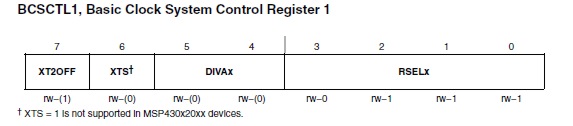
crystal oscillator There are several routines out there. If you search 'Set_DCO' and 'SetDCO' in Google, you will find them. What may not be obvious is that the routine will change according to the family of devices you are using. If you look at x2xx basic clock, you will find this:
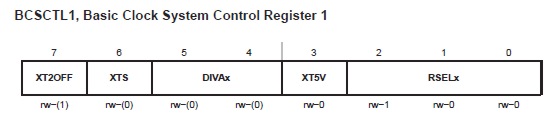
And if you look at x1xx basic clock you will find this:
Toward the lower end of the Set_DCO routine you will find the line:
cmp.b #0x87,&BCSCTL1
; Can RSEL.x be increased? This is written for MSPGCC so you will need to modify it according to your flavor of assembler. It is written to be called from 'C' with the delta value and saves most of the timer state on the stack.
 (FT232RL)
OCTOBER
1,
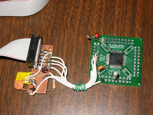
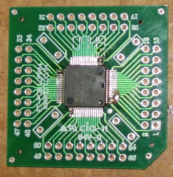
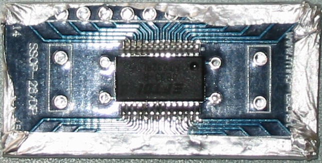
2009 Soldering, One more Time Here I've
taken
some photos of my third chip. This went very quickly now
that I am more
comfortable with this. I'd say start to washing the flux
off, this is
less than a ten minute job. It is about being
comfortable with what you
are doing. A little practice will get you there fast.
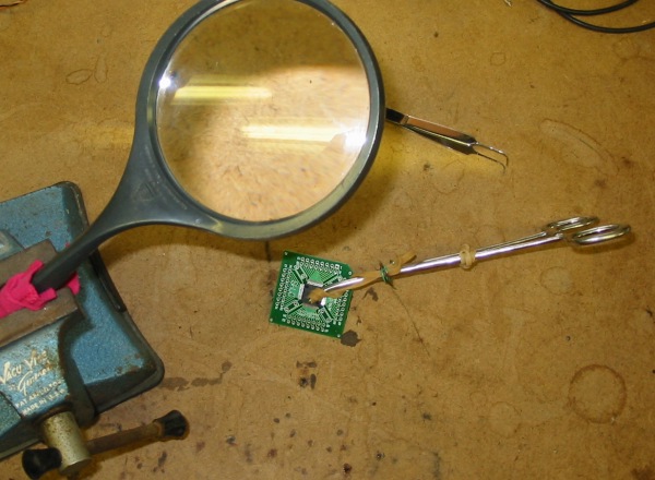
Before
picking up
the forceps get that chip aligned under your magnifying
glass. Hold the
alignment on one side of the chip with your finger then
put the clamp
on. There are two rubber bands on the clamp. One to the
right for a
light clamping pressure. The one on the left is just a
couple of wraps
on the tip and the rest is held out of the way with a
piece of wire.
This puts pressure from the tip on the center of the
chip where the
metal part of the clamp would land on the edge of the
chip. Now you can
pick it up by the forceps and take a good look at your
alignment. Yes,
a hands free magnifying glass is necessary.
When you
are
satisfied with the alignment put a drop of solder on the
four corners
and then you can take the clamp off. To make sure the
chip stays seated
down I've added four more dabs of solder. You can see
that here.
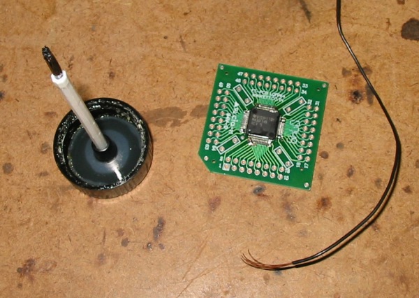
Now it is
time to
solder it down. Be liberal with that flux. I didn't use
anything fancy,
just some off the shelf GC liquid flux. You need the
flux because you
will not be adding solder but instead, removing it. That
piece of
stranded is #22. I like it better than wick because it
is not so
intrusive. Just lay the wire along the pins and gently
work your iron
down the row on top of the wire. You will see lots of
solder wick into
the wire. sop up as much as you can and take a look
under a microscope.
If you see any bridging do a little more wicking. When
you are
satisfied, finish up by touching your iron down the pads
and you will
have a very professional looking job. You will see an
example of
'touching' in the Washburn video. It should look like
production work
under the microscope.
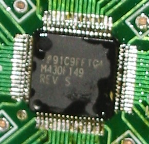
Here it
is
before washing the flux off.
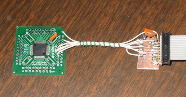
The JTAG
test,
works fine! Thanks, Dan. Copyright
© 1996 - 2009, http://www.lakeweb.net/MSP430/index.html |