|
|
Charging Solar
Batteries Inexpensively |
|
|
|
|
|
January 19, 2017 I have a friend that lives off grid
in a beautiful country setting. In the winter when it
rains there is just not enough sun to keep the batteries
fully charged. The charger in his old inverter is rated
30 amps @ 24 volt system. And it is a bit cantankerous
so will cut out if it doesn't feel that the generator is
not providing the proper line voltage. So we started
looking for a solution. First thing that comes up is
finding a used forklift charger. They are around, as I
recall for as little as $.20/watt. But those old
chargers use a line wound iron core transformer. That
makes then pretty heavy and not so efficient. Also, if
it goes belly up, that is it unless you have two of
them; lights out... Then I thought about those
inexpensive power supplies on Ebay used for CNC and
everything else. But these supplies are constant voltage
and won't run up to the 29 volts that is required to
charge a battery bank. It just means they need to be
modified. Great thing is that if you are running a bank
of these things and one goes out, the rest of them just
keep on working. We are running with ten of them. So
150A * 28V is 4200 watts of charging power. Best part, if one supply fails it
does not bring the whole thing down. You just loose 10%
of capacity. And the price point, about 7 cents / watt
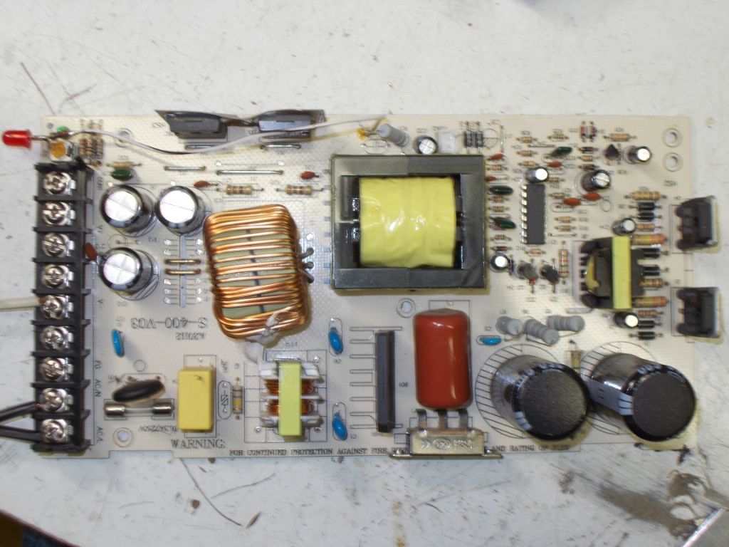
for new equipment! Hard to beat this solution. Here is the board pulled from case: |
|
|
|
|
|
|
|
|
|
|
|
They are built reasonably well built,
especially for the price. This one is rated 15 Amps @ 24
Volts and in the door, ~$25. The weakest point on these
supplies is the input line filter marked LF2 on the
board. I've changed these out as they burn up as we so
far have lost like one a year. I use something like
this, beefy. But in this application it is probably not
even necessary and can be jumped out. |
|
|
|
|
|
|
|
|
Pull R16. It is a bleeder and a phantom load. You don't need to drain the batteries unnecessarily. I added the red LED grounding it to
the voltage adjuster pot and running a wire, via a 220
ohm resistor to R37. This is the running power supply
indicator as the board's green led will always shine
from the batteries. Solder a 10K resistor across R40. This will allow you to set the output voltage above 30V. If you have a puny looking filter
you can just jumper it out. If the supply has a thermostat for
the fan, usually floating inside the large output
inductor, just jumper it out and have the fan run full
time. There is no point in doing any other way in this
application. And most important, trimming the
'J' jumpers. I've seen just one of these supplies that
did not need trimming. Because the supplies will be
running constant current this part of the circuit must
be within specifications. I've damaged a few of these
by not setting this early on as I assumed the current
limiter was good to go. I'd lost the driver
transistors and emitter resistors. So far I've been
able to quickly repair these. So once the
modifications are done, fire it up with a load that
you can adjust. I just used a heater core and set the
jumpers to pull the current I was looking for. Get a couple of small aluminum
plates to put onto your switchers and the output
diode(s). I've seen these come with a one or two diode
configuration. As long as you don't run with a full
load for more than 10 or 15 seconds at a time, they
will work fine.
Yes, this is over 400 watts out. But I've tested at 450 watts out which requires 480 watts in. So the supply will dissipate 30 watts fully loaded. With the fan the output transistors and output diode just get warm at this power. The rating on the output transistors is more than adequate for this service. And the proof is in the pudding, the supplies I've modified are all holding up fine. They are used for 30 to 60 minutes at a time. I'll get a picture of the bank of supplies and put it here: 
Thanks, Dan. (pubdan5 at lakeweb dot
net) Copyright
© 1996 - 2017, http://www.lakeweb.net/content/charger.html
|