|
I had been looking for a rotary
converter for my machine tools. I've been getting away
with a capacitor converter I got with my mill. But I
knew the motor was poorly powered and getting hotter
than necessary. Then I upgraded my lathe and needed a
proper power supply. By reading, Optimization
of phase converter parameters and effects of voltage
variation on their performance 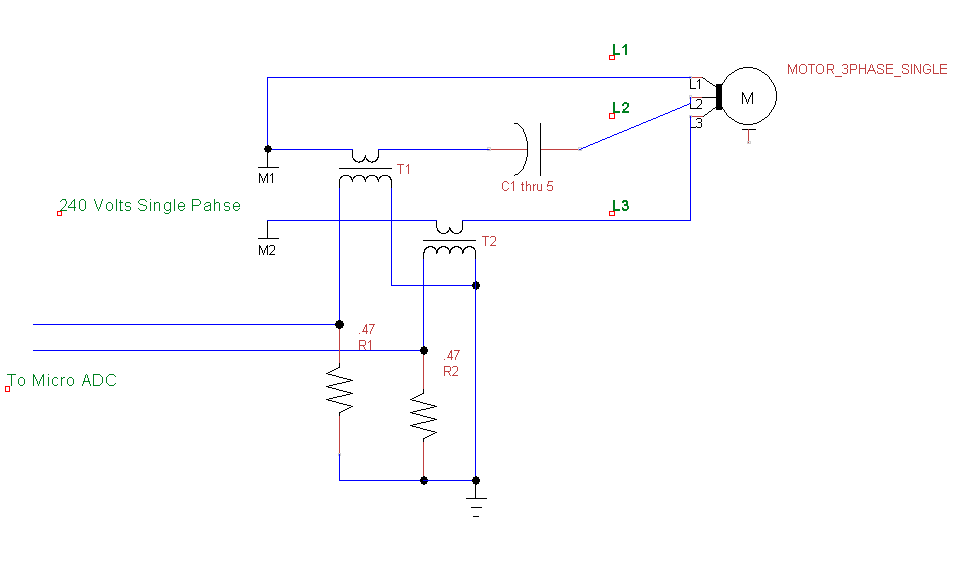 In this application the rotary transformer was necessary to avoid hacking the electrical panel of the lathe. It has a set of contactors for low and high speed, and reverse so three phase power needs to be present before starting the lathe. Also, the load on the lathe and mill are highly variable. Rotary converters have a recommended motor size of twice the highest load. The motor on the lathe has a very high starting inertia and the motor is rated at 6hp. That means the recommended size of the 'pilot' motor is 12hp! So my solution was a hybrid system that uses a 3hp idler motor and capacitor switching to meet the demands of the tool motors. It turns out this works extremely well!  This is the high voltage side of the system. Five 40 uF capacitors, four are switched with TRAICs. There is always a requirement of one capacitor to run the rotary transformer. This was spread over several square feet on the bench during development. When I was satisfied with the system performance, I built this package. The microprocessor is electrically isolated from this by using current transformers and photo-coupled drivers for the TRIACs. The microprocessor also controls the relay on the lower left of the package, the single phase 240 volt supply. The output is for the rotary transformer('pilot motor'), and two loads. This is what development looked like. I set up a temporary lab in my metal shop. 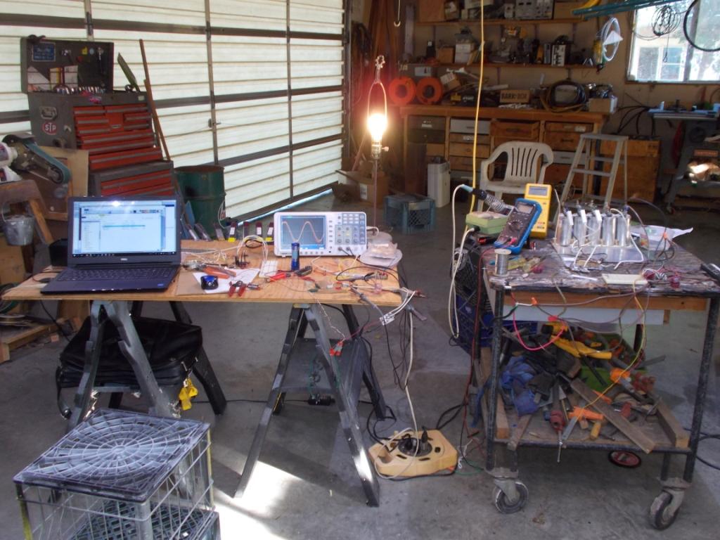 Theory of Operation There is a switch wired to the microprocessor for power on. The micro will set all the TRAICs on and close the input relay. This will quickly bring the 'pilot' motor up to speed. As the motor approaches synchronous speed, the current on 'L2' will increase and exceed the demand at 'L3'. Every cycle the microprocessor takes a current measurement of the two current transformers. When the current at 'L2' exceeds 'L3' a capacitor is switched out of the circuit. This happens very quickly, but the pilot motor does anything but struggle to come up to speed. The pilot motor on its own runs quite nicely on one 'run' capacitor. So the fifth capacitor in the bank is permanently wired to 'L2', there is no need to switch it. If a piece of equipment is turned on, the starting load causes the current on 'L3' to exceed 'L2' by more than twice. every cycle a capacitor is switched in circuit until 'L2' is at least half of 'L3'. When a high speed demand from the lathe comes on line, it will switch in two or three caps to balance the current. Note that motor is larger than the pilot yet it does not need as much starting capacitance to start up as the pilot did. This is because the pilot, 'rotary transformer', is now supplying current in the proper phase to 'L2'. Even though the pilot is undersized in conventional rotary converter terms, the switching of capacitors picks up the slack. 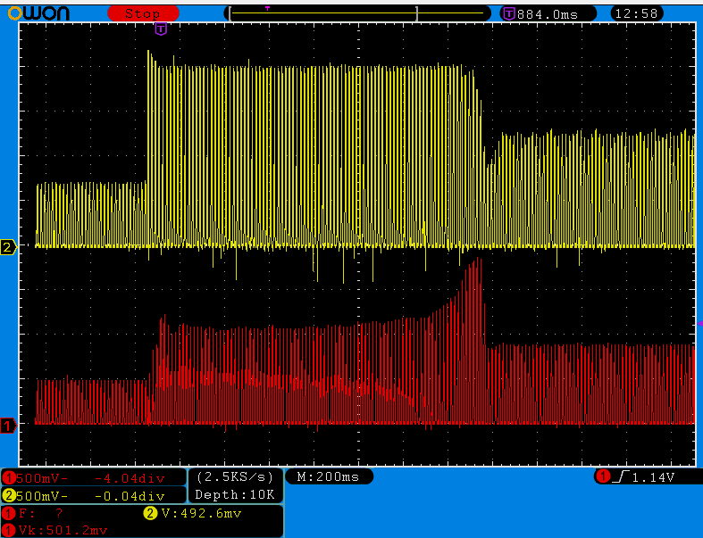 In this snapshot the lathe is turned on high, motor at 3600 R.P.M. The motor is switched on at the left and the current ratio of L2/L3 drops to less than half. Capacitors are switched in until this ratio is greater than half. In this case three capacitors are switched in. As the motor comes up to speed, capacitors drop back out as the ratio exceeds one. It turns out that the last one does not drop out as two capacitors are the appropriate 'run' for both the motors. And I've tested by loading the pilot, a capacitor will switch in as more 'run' current is needed at 'L2'. This arrangement works so very well. It exceeds my expectations. The motors start up as well as if hooked to a true three phase supply. And because run capacitors will switch in when needed, there will be ample torque available when the demand is present. Details This is a schematic of one capacitor switch. There are four of these. The resistors in series with the capacitors are required. The TRIAC drivers have a best guaranty of zero crossing within 20 volts. Just about any voltage across the TRIAC will mean current delivered directly from the capacitor, theoretically at infinite current. It will take the TRIACs out. I got what I could on EBay so used two 1.8 ohm@10watt resistors in parallel per capacitor switch. Important BOM: 40 uF @ 440 volts oil bath run capacitor. Not start capacitors! BT137X-800 or equivalent. Should be able to surge to 100 amps. MOC-3063 Don't skimp on this! The rest of the parts can be adjusted as seen fit. 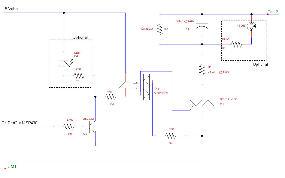 The Current Transformer output is amplified to utilize most of the ADC input range. The ADC input is set for 0-1.5 volts of input. By using rail to rail op amps, (TLC272), only two resistors to set the gain are needed. 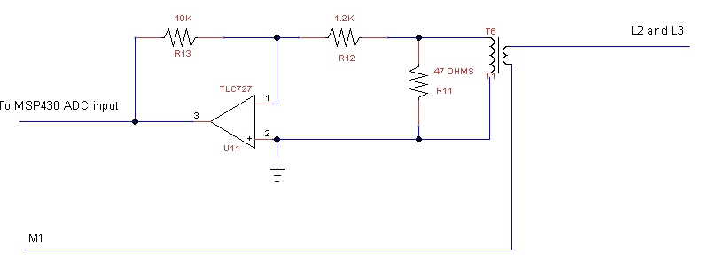 The current transformers, (CTs), are wound on a couple of salvaged powder cores that were used for AC line filtering. There are 48 turns, (4 wires x 12 for easy winding). And the burden resistors are .on the order of half an ohm( .47 ). The cores I used are about 1-1/4" across and 1/2" thick. You should be able to get away with about anything as long as you put enough turns on it. Test it by passing a turn to a bathroom heater on a variac. The output should follow the voltage to the heater with a clean sinewave on a scope. 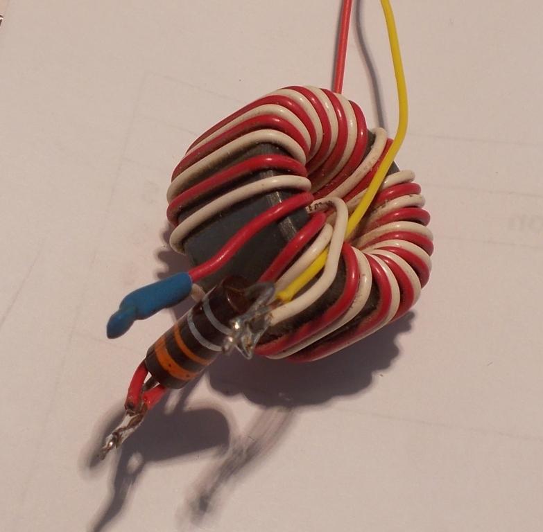 Because of the extremely low output impedance of the CTs there is no need to average the sampling or filter at the op amps. The signal is noise free. The low voltage power supply starts with a 12 volt 1 amp switcher. The heavy user is the main relay. Then a 7805 for 5 volts, to an MCP1702 for the micro's 3.6 volts. Bringing it all together... 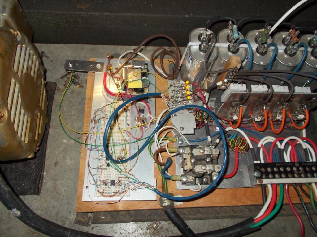 Yea, it is running on a prototype board. It is a new, never sued before board; so the contacts are all very tight. I have seen connections get flaky on boards that have had some use, I wasn't willing to see a failure sooner than later. (schematic and more.......) Implementation Next will be a set of schematics and the source code for the microprocessor. I can develop for the ARM but when ever it is a small job, no real demand for uP horsepower, I typically reach for an MSP430. I keep a handful of MSP430G2553s in the DIP package around. I didn't check but I'd imagine I'm utilizing at less than 5-10% with a 1Mhz clock. Here is the source for this first version. I will improve this like a crowbar on the relay driver in the case it were ever to short out. Watch dog multiple points and fault on any inconsistencies. Thanks, Dan. Copyright
© 1996 - 2018, http://www.lakeweb.net/three_phase/index.html |