|
Radius/Maxtrac/Maratrac Ham Conversion
I have had a Radius sitting on the
shelf for some time. I didn't give it a lot of thought
as I didn't want to hassle with Motorola's propriety
programming. Then I started looking and thinking about
what I could do with it. As I recall the radio had
something wrong going on so I started by making sure the
receiver would work well in the Ham band. I also had a
second RF board for UHF. This radio has a VHF PA so I
started with that.
The RF Board Connector
The start. June 17, 2014
First thing was to make a tool to
work over the RF boards.
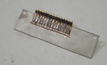
This is a right angle header soldered to a piece of one
sided PC board. I cut the lines with a Dremel cutoff
wheel. Here it is with power applied.
Because it lays flat with the board, it doesn't get in the
way when flipping the board over.
So you can see two pieces of coax. The one going under is
connected to the RX input port. the lighter one is tacked
to the input of the mixer. The impedance here is very
close to 50 ohms. Now I can sweep all the way through as
the active device has power.
The Front End
I was suprised at how nice the VHF board looked. I was to
understand that an HLD4322B was not a great Ham band
board. But this is what I saw.
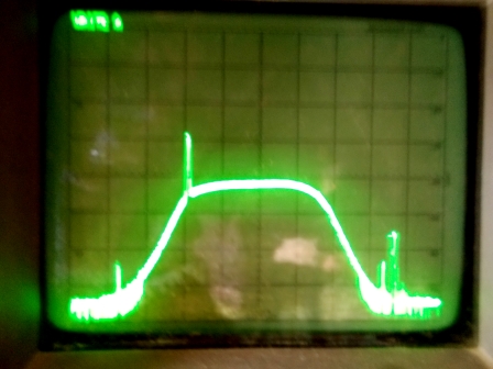
The marker is at 140Mhz and the sweep is 10Mhz per
division. There is only the slightest tilt at 146Mhz. The
UHF board was a HEL4435A, it did not look good at all. But
the front end on this board had aluminium slugs in the
coils. By backing them out I got this:
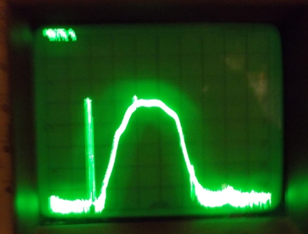
The marker is at 430Mhz and the sweep is 20Mhz per
division. The big nasty to the left of the bandpass is the
LO running dirty
The Synthesizer
The next go round. July 1, 2014
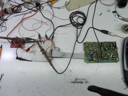
On the left, red circuit board, is a Texas Interments
Launch Pad. The whitish board is bare copper, and just
like the RF plug, it has been cut with a Dremel enough to
hold down parts. There is just a header and five one
transistor level shifters, for now I'm just using the
first three. The logic on the RF board is a full 9.6 volt
swing while the MSP430 is 3 volts. Except for the VHF low
band board, the synthesizer is a MC141558. It should be a
direct replacement for Mot's RF division 84704M75. So far
it looks like the low band chip was produced only for
these radios. But once I bench a low band board I would
expect the logic to work much like the commercial line of
chips. So the cable off the RF board is hooked to fR,
the pin 13 test point of the synthesizer. Pumped in a 2880
divisor to the ref counter
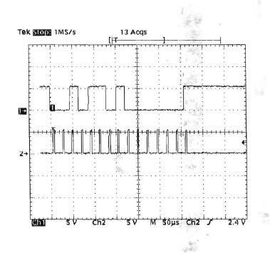
And...
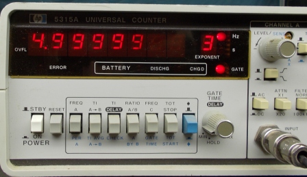
5Khz steps. The Launch Pad is a quick and easy way to
start a project. Even if you move beyond the Value Line
MSP430s, your code will port right over. Here is a link to
the source for this first test.
SynthesizerFirstTest.c
The Synthesizer Part II
Sunday Fun. July 6, 2014
I wanted to finish up the synthesizer code. I'm getting a
low band radio before long so the code will cover all the
bands. The VHF wasn't a big deal, I knew what the
commercial version of the chips where. I got thrown with
the UHF board for a bit. They used a 127/128 prescaler and
the MC12017 is a 128/129. So I was coming up off on the
frequency selection. My hard copy of the maxtrac manual
doesn't have any discussion but I remembered the manual on
repeater-builder did. Sure enough they disclosed info
about the prescaler and had a pretty straight forward
formula that I just copied into my code, works fine.
SynthesizerWorkingCode.c
Next is to measure and stash the temperature compensation
voltages for the reference oscillator.
Thanks, Dan.
Copyright
© 1996 - 2014,  Highlands
Electronics All Rights Reserved. Highlands
Electronics All Rights Reserved.
Page created: 17
jun 14 rev: 6 jul 14
http://www.lakeweb.net/Radio/radius1.html
|
